DCDC Converter
HDC24
Converts unstable power supply to stable 24V.
The converter resolves the voltage drop issue in the long wiring over 10 m, eliminating the restriction for the power supply panel location.
Step up/down type:
– Input [18-30 V]
– Output [24 ± 2 V, adjustable]
Input protection:
reverse connection, surge current, overvoltage
Output protection:
overcurrent, overvoltage
View more
Specs.
| [Input] Voltage range | 18 V to 30 V |
|---|---|
| [Input] Efficiency | 93 % (typ) |
| [Input] Current | 6.0 A |
| [Input] Surge current | 8.0 A |
| [Output] Voltage rating | 24 V |
| [Output] Max current | 4.0 A |
| [Output] Instantaneous max current | 5.8 A |
| [Output] Max power | 100 W |
| [Output] Variable voltage range | 22 V to 26 V |
| Current suppression (output) | 6.0 A |
| Overvoltage protection (input) | 31.0 V |
| Parallel run | Not allowed |
| Serial run | Allowed |
| Body size | W: 74 mm H: 100 mm D: 26 mm |
| Weight | Approx. 300 g |
| IP code | IP65 |
| [Input] Voltage range | 18 V to 30V |
|---|---|
| [Input] Efficiency | 91 % (typ) |
| [Input] Current | 8.0 A |
| [Input] Surge current | 16.0 A |
| [Output] Voltage rating | 24 V |
| [Output] Max current | 8.0 A |
| [Output] Instantaneous max current | 11.6 A |
| [Output] Max power | 200 W |
| [Output] Variable voltage range | 22 V to 26 V |
| Current suppression (output) | 12.0 A |
| Overvoltage protection (input) | 31.0 V |
| Parallel run | Not allowed |
| Serial run | Allowed |
| Body size | W: 74 mm H: 100 mm D: 40 mm |
| Weight | Approx. 500 g |
| IP code | IP65 |
| Safety Standards | Conforms to UL60950-1 Conforms to EN60950-1 |
|---|
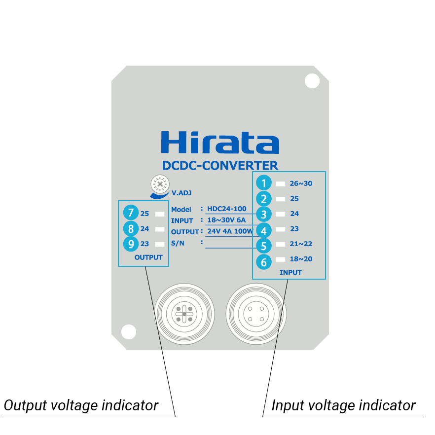
| (1) 26 to 30 [blinking red] |
28 V ± 100 mV < V V < 30 ± 100 mV |
|---|---|
| (1) 26 to 30 [solid red] |
26 V ± 100 mV < V V < 27.9 ± 100 mV |
| (2) 25 [solid green] |
25 V ± 100 mV < V V < 25.9 ± 100 mV |
| (3) 24 [solid green] |
24 V ± 100 mV < V V < 24.9 ± 100 mV |
| (4) 23 [blinking green] |
23 V ± 100 mV < V V < 23.9 ± 100 mV |
| (5) 21 to 22 [solid red] |
21 V ± 100 mV < V V < 22.9 ± 100 mV |
| (6) 18 to 20 [solid red] |
18 V ± 100 mV < V V < 20.9 ± 100 mV |
| (6) 18 to 20 [blinking red] |
V < 17.9 ± 100 mV |
For the indicator layout, refer to [Feature] > [Input/output voltage LED indicator].
| (7) 25 [blinking green] |
25.5 V ± 100 mV < V |
|---|---|
| (7) 25 [solid green] |
24.5 V ± 100 mV < V V < 25.4 ± 100 mV |
| (8) 24 [solid green] |
23.5 V ± 100 mV < V V < 24.4 ± 100 mV |
| (9) 23 [solid green] |
22.5 V ± 100 mV < V V < 23.4 ± 100 mV |
| (9) 23 [blinking green] |
V < 22.4 ± 100 mV |
Configuration
-
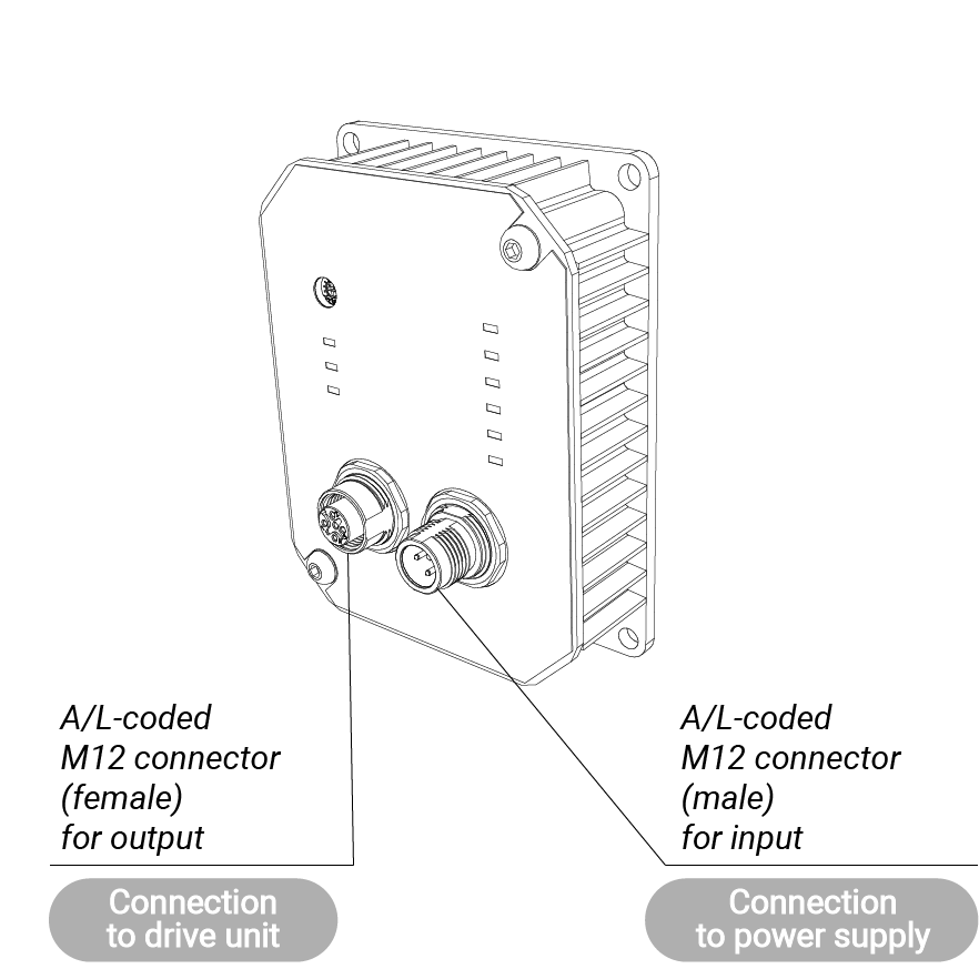
Main body

Feature
-
Input/output voltage LED indicator

The LED illumination pattern provides visual indication of the current input/output voltages individually.
*To obtain the exact value, please use a measuring apparatus such as a voltage tester and an oscilloscope. -
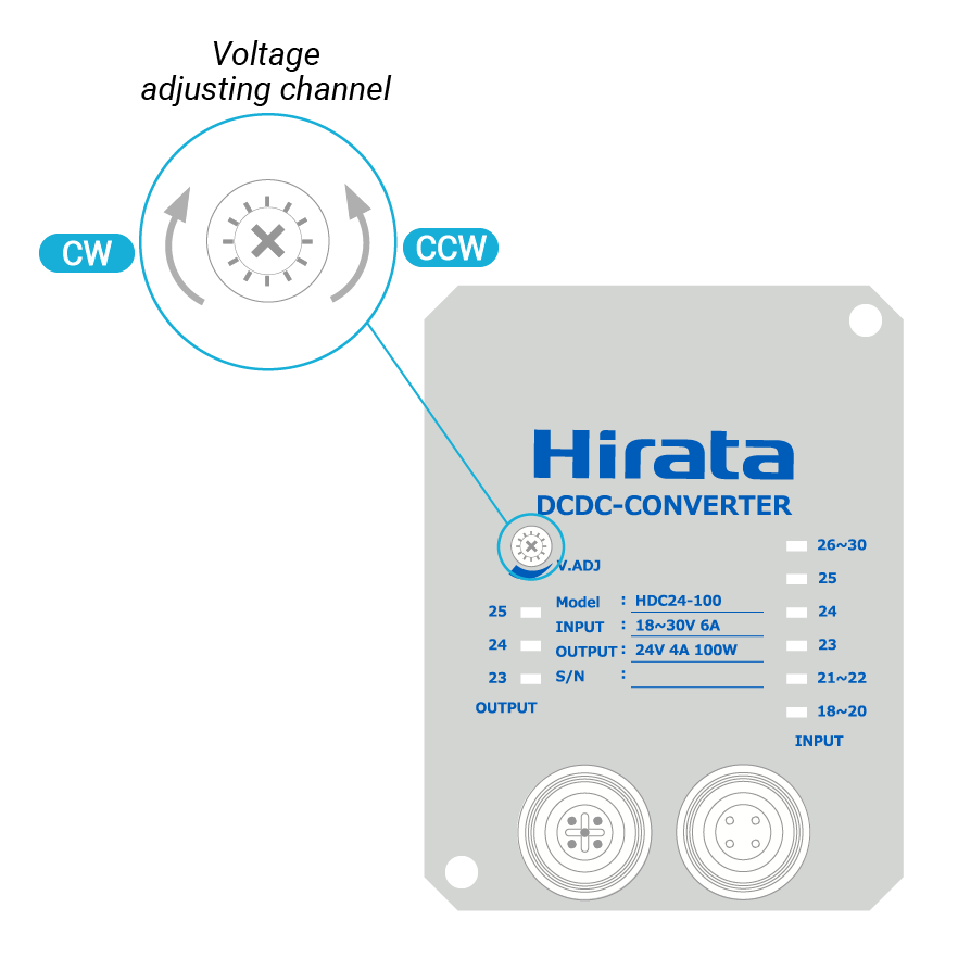
Voltage control by voltage adjusting channel

- Turn CW: Step up.
- Turn CCW: Step down.
Contact
For more information, please contact us.


![[HDC24]DCDC Converterthumbnail_0](/wp/wp-content/uploads/2022/03/OP-dcdc-186x186.png)
![[HDC24]DCDC Converterthumbnail_1](/wp/wp-content/uploads/2022/06/HDC24_feature_en2-186x186.png)
![[HDC24]DCDC Converterthumbnail_2](/wp/wp-content/uploads/2022/06/HDC24_feature_en1-186x186.png)
![[HDC24]DCDC Converterthumbnail_3](/wp/wp-content/uploads/2022/06/HDC24_feature_en3-186x186.png)
![[HDC24]DCDC Convertermain_0](/wp/wp-content/uploads/2022/03/OP-dcdc.png)